L.N.W.R.
In defence of "H0" - by J. K. Nelson

From The Model Railway News, October 1952.
Correspondence in The Model Railway News about "H0" 3.5 mm to 1 ft scale models suggests that interest in this scale is still maintained and I know of one or two modellers who are seriously considering its possibilities. This article is an attempt to describe briefly how to adapt existing parts for this scale.
My L.N.W.R. 3.5 mm scale model at the headquarters of the Ilford Junior Railway Club has used much standard "00". equipment, suitably modified.
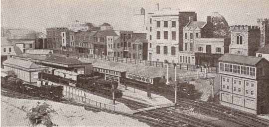
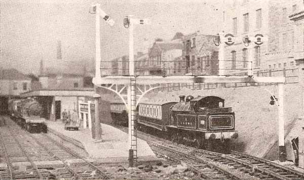
Track is standard Peco Individulay. The gauge is correct 16.5 mm. The Peco chairs are under size for "00" and they are not far out for "H0". The rail, of course, is over size but it does not look too bad as seen in Photograph 1 and Photograph 2.
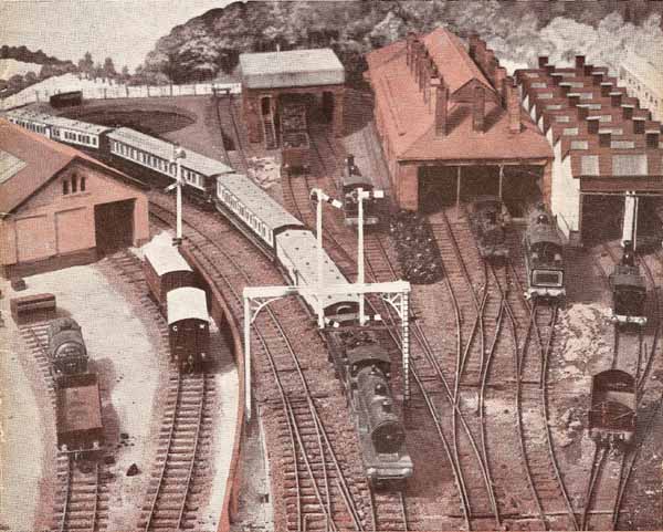
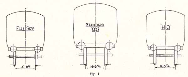
As standard "00" track had been accepted, the use of commercial "00" wheels seemed logical. It is unfortunate that the overscale width is so obvious, but when used for 3.5 mm scale on track of the correct gauge (16.5 mm), the total errors are considerably less than when using 4 mm scale rolling stock on the same gauge. Photographs 1 and 3 being more or less "end on" might be expected to show things at their best, but Photograph 2 showing part of the junction station and Photograph 4, part of the goods yard and engine sheds, show that the modifications are not too bad. Ken Springate has prepared Figure 1 to show more clearly what is meant. The three coaches are all on 16.5 mm scale track. The first is a full size coach reduced in proportion, the third is the same coach to a scale of 3.5 mm to 1 ft, but using standard "00" wheels. The second is the same coach to "00" standards. Note that the track gauge in all three cases is identical. The wide wheels look shockingly bad but the drawing purposely shows things from the worst viewpoint. Normally, the models are not inspected close enough for the error to be unsightly, but "00" rolling stock on 16.5 mm track always looks narrow gauge, which, in fact, it is. If very sharp curves are necessary, metal can be removed from the inner faces of the solebars to allow for the necessary increased bogie swing. This has not been necessary on my coaches. They all negotiate the curves without trouble.
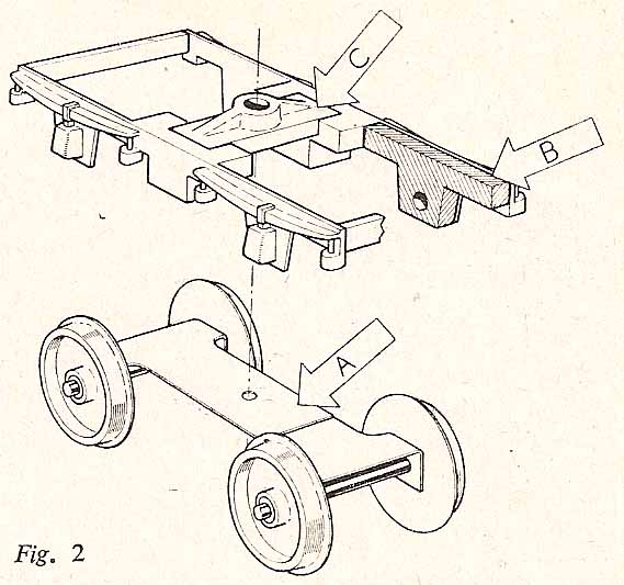
I hope no one thinks that I am suggesting that this scale is the only right one. There is in our hobby plenty of room for all points of view. No one, therefore, should be offended if encouragement is given to those who are again considering the merits of "H0". Supplies of commercial parts, if not plentiful, are adequate. Let us see what we have. 16.5 mm track is obtainable anywhere. Standard "00" motors can be used without alteration. Locomotive wheels are available in a good range of sizes. Coach bogies, until recently, were a bit difficult, but the aero springing unit has solved the problem. Look at Figure 2. The unit, complete with wheels, is shown at A. This is as purchased except for the shortenings. The spring is cut through, overlapped and soldered to give the required wheel spacing. The unit is made for "00" wagons and has 12 mm wheels which are the correct diameter for "H0" coaches. Most of my coaches are mounted on 9 ft 0 in bogies for which standard "00" 8 ft 0 in bogie sides are used. This makes the wheel spacing 0.5 mm out, which is not too bad. Luckily, the cast springs are very nearly the correct length for "H0". The axleboxes are not the right shape, but I have not tried to alter them. Metal is filed away as shown shaded by B. Nothing of the bearing holes remains so there is no possibility of the axle ends binding. After removing metal from both ends of C, the parts can be soldered together in a suitable jig. Allowing for 0.5 mm lateral axle play, the castings can be assembled to scale width. After inserting suitable shims between the axle ends and side castings, A is soldered direct to the underside of C. On the drawing, the pivot hole is shown in A but it is best drilled after soldering.
Trevor Leake must be thanked for the photographs illustrating this article and Ken Springate for his help generally and Figure 1 in particular.